Casting Recap
Barrel Alignment
Barrel Exterior
But Weight, There's More
Barrel Liner
Completion and Test Fire
Problem 1: Jamming
Problem 2: Sight Alignment
Problem 3: Unscrewing Barrel
Finishing Up
Conclusion
Appendix 1: Optic
More articles
As mentioned in the introduction, I started putting together a dedicated .22 barrel before the .22 conversion kit group buy began. Had I known that someone would soon be making barrel inserts designed to fit down a standard .308 bore, I would have left the Argentine barrel unmolested and just used a standard .22 barrel insert. However, I now had a liner and a reamed-out barrel and didn't want to waste them. Kurbelgehause was kind enough to sell me a chamber insert that hadn't yet been fitted to a barrel liner, which I reamed out to 5/16 so that it slid onto the rimfire liner. I had everything required to make a custom insert.
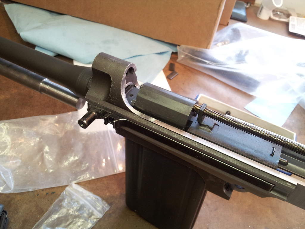
It just hadn't been assembled yet. Although I'd used the .22 liner and chamber insert to test barrel alignment, this was done while they were still individual parts. I would screw the barrel on, slide in the liner, and then slip the chamber insert over the end of the liner that stuck out of the chamber inside the receiver. Actually, what usually happened was that I'd try to slip the chamber insert over the liner, notice that it jammed on the rails due to barrel misalignment, then say a bad word and turn another eccentric.
But eventually the chamber insert fit into place. It was time to attach it permanently to the liner and add some barrel-like attributes to the liner itself; specifically, chambering one end and crowning another.
Get a Grip
There was only one problem: Rimfire barrel liners are really thin. This one had sides only about 44 thousandths thick, so it probably wouldn't react well to aggressive chucking in the lathe. Liners are probably intended to be permanently inserted into a barrel prior to chambering and crowning, but this one would remain removable. I didn't want to use hand tools to chamber and crown, so something had to be done to allows the delicate line to survive lathe work.
Something was done.
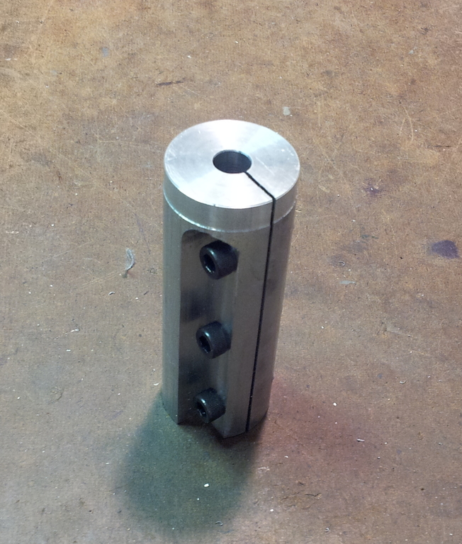
I made a liner gripper out of aluminum to hold the liner with even pressure around its entire circumference. Tightening down the cap head screws gradually increased the holder's grip on the sleeve.
The liner holder itself could survive chucking in the lathe, which meant the liner could pass through the spindle. I also built an extremely sophisticated device to support the liner at the rear of spindle.
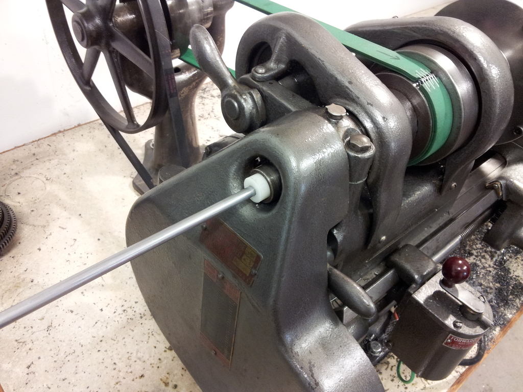
I turned the outside diameter of the holder true to the reamed pass-through hole to allow the holder itself to be used for indicating. Although this method worked, it would be more exact to indicate off a precision-ground bore insert; I plan to use that technique for any future liner work.
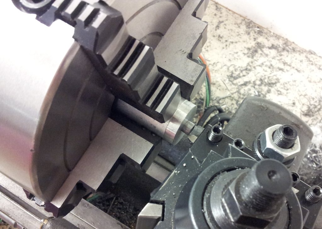
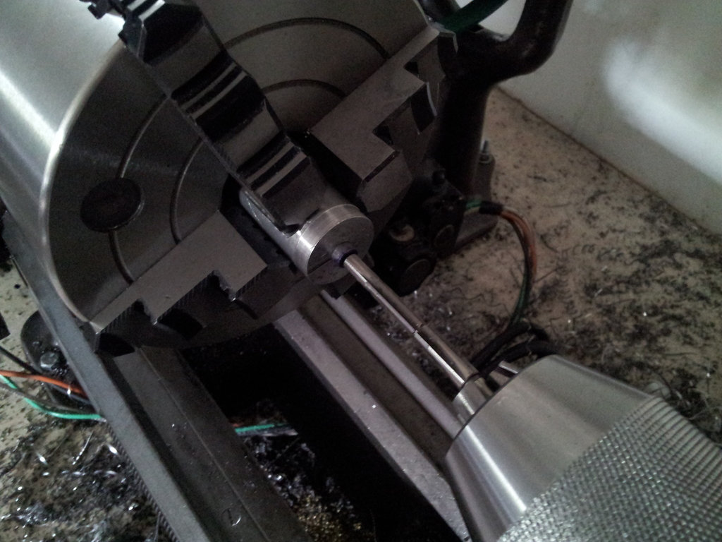
For now, though, the liner gripper allowed crowning and chamber-cutting in the lathe, even though it looked a little silly to see the massive chuck and large toolpost clustered around the tiny bit of protruding liner.
Crowning
Crowning was simple enough once the setup was established. It started with cutting the liner to length.
Cutting: simple. Cutting the right place: slightly more complex.
Then I just faced the sawn edge of the liner true, followed by setting the compound at 11 degrees and cutting the crown from the inside out.
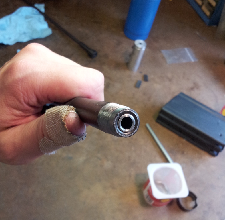
Only one of these crowns matters.
Chambering
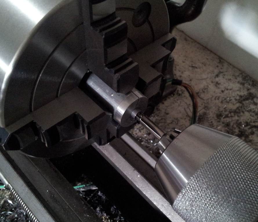
Chambering was nearly as simple. The chamber end of the liner was chucked up and faced just like the crown, followed by feeding a .22 LR reamer into the chamber.
As with dialing in the liner, the methods I used here have room for improving precision. I chucked the reamer in the tailstock but kept it loose to allow some wiggling for alignment, but otherwise relied on the lead section of the reamer to align itself to the rifling.
Sorry about the dimness of the photos, by the way. The power was out at the time, so I just opened the shades and turned the chuck by hand.
Reaming continued until a .22 GO gauge fit comfortably into the liner. It wasn't necessary to take the reamer all the way to its shoulder for reasons which will be discussed in the next section.
Chamber Insert
The .22 bolt has a flat face, so headspace is determined by how deep the liner is recessed into the chamber insert. This allowed me to do something uncharacteristically clever when it came to setting headspace and soldering the liner in place.
One concern about setting headspace while permanently joining the chamber insert and liner was balancing worries about also permanently joining a headspace gauge to the entire assembly versus setting headspace and then having an errant bump throw it entirely off. The liner gripper ended up letting me avoid both eventualities.
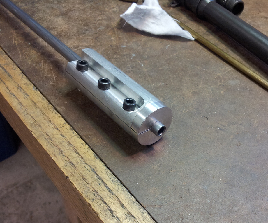
Here's how it worked. I clamped the liner gripper in a bench vise and applied enough tension to the liner to require deliberate effort to slide it back and forth. Then the chamber insert went over the liner until it butted up against the gripper. A GO gauge went into the liner and a parallel was pressed against the base of the GO gauge until it was flush with the surface of the chamber insert.
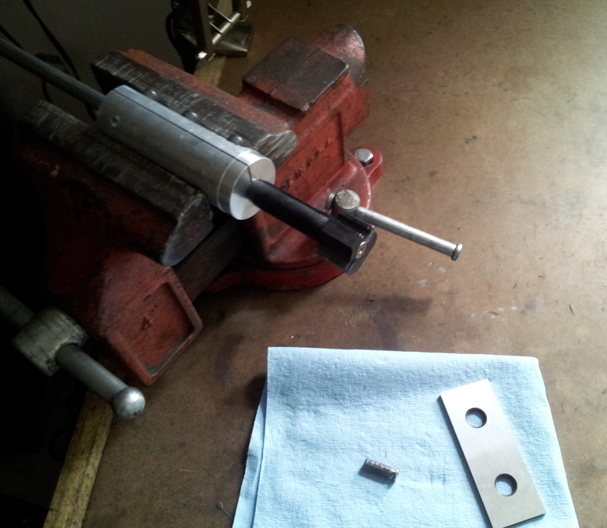
With headspace thus established, the liner gripper was tightened down to prevent the liner from moving. Now it was possible to remove the chamber insert and paint the liner with flux. When I put the chamber insert back on the liner, all that was required to restore the original headspace alignment was making sure its front end touched the liner gripper.
By design or happy accident, the chamber insert has two small drill holes on top of it, the perfect size to receive tiny chips of solder. All I had to do was heat the chamber insert with a torch until the solder melted and wicked into the gap. I know the solder got good coverage because it appeared between the insert and liner at both the front and chamber ends of the insert. As a nice side effect, the aluminum gripper made a great heatsink; no heat was transmitted down the barrel and the solder immediately solidified at the point where it hit the gripper, preventing the liner from becoming attached to the gripper as well.
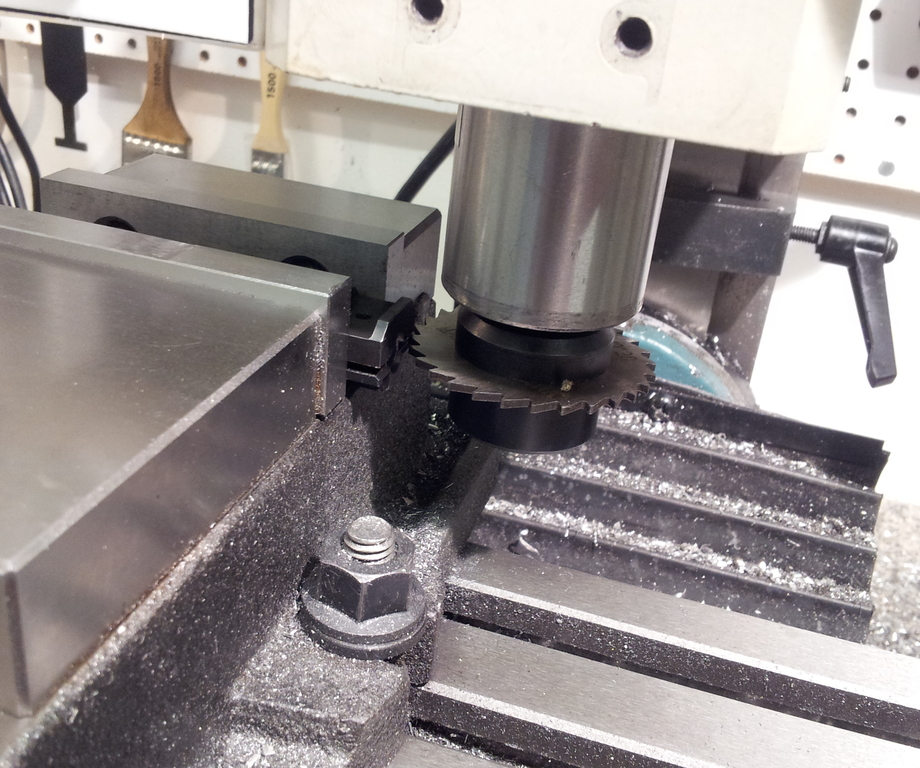
All that remained to complete the liner was cutting the extractor groove in the liner using a slitting saw. I assumed that the sides and bottom of the chamber insert were square to the bore axis and used those to align it in the milling vise.
Not something I saw before.
Faith in Kurbelgehause's machining abilities was not misplaced: The extractor cut went well, aside from burrs kicked up by the slitting saw.
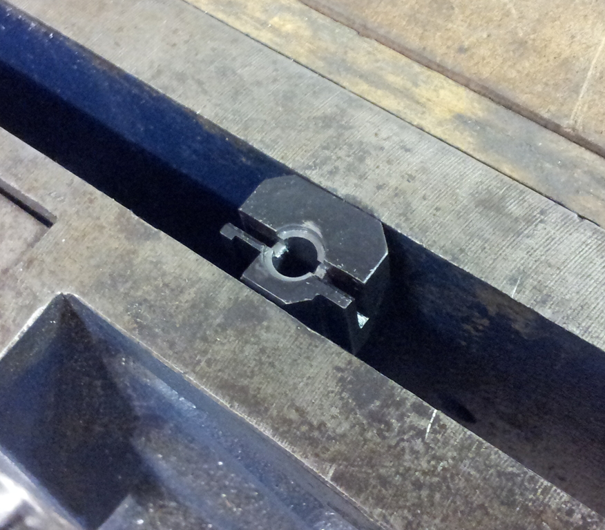
The burrs were easily removed by dropping in the chamber reamer and giving it a twist. Now it was possible to check headspace using the actual .22 bolt.
For once, there were no nasty surprises. The bolt closed flush on a GO gauge and didn't on a NO-GO. The barrel liner was complete.
Afterthoughts
This was the first "barrel" I'd ever made. True to form, it was atypical. Some usual operations were not required (e.g. external contouring); but in their place were problems that don't even appear for regular barrel-making, like figuring out how to hold the darn thing in the lathe. Maybe I should try turning a regular barrel to see how that compares to building the liner.
Some may be wondering if the low-temperature silver solder used to affix the chamber insert to the barrel is sufficient to keep the liner in place. I think so. Assuming that full breech thrust from a firing .22 cartridge were to be placed on the liner (which it won't, as pressure is going the opposite direction), and further assuming only 50% coverage of solder (which is unlikely given observed wicking), there's still nearly a 10X safety margin. It's true that the solder will flow at 475 degrees Fahrenheit, but I don't believe it's possible even to approach that temperature: The liner and chamber insert are ensconced in a gigantic steel heatsink, and the kit can fire at most 20 rounds rapid-fire before having to change magazines, then only a further 20 rounds before both magazines must be reloaded. Besides, I don't like to magdump and my FAL is, alas, not full-auto.
But concerns about melting solder were in the future; they'd have to wait until the dedicated .22 was completed and test fired.
email: hidi.projects at gmail.com