Casting Recap
Barrel Alignment
Barrel Exterior
But Weight, There's More
Barrel Liner
Completion and Test Fire
Problem 1: Jamming
Problem 2: Sight Alignment
Problem 3: Unscrewing Barrel
Finishing Up
Conclusion
Appendix 1: Optic
More articles
The heavy Stolle muzzle device had required modifying the barrel to fit, but that wasn't the last time the lathe would be spun up in pursuit of greater weight--and not even the last time for the barrel assembly.
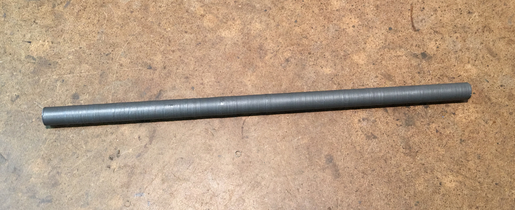
Gas "Tube"
At first I considered filling a standard gas tube with molten lead, but decided against the idea on the grounds that it would be hard to reduce weight if it turned out too heavy, it would use up an otherwise serviceable gas tube, and it sounded like the preface to the story about how one acquired a disfiguring scar. Filling a gas tube with lead bullets would be too rattly, as would using a steel rod unless it was turned to exactly the right diameter and length for the interior of the tube. And if I was going to fire up the lathe to make the gas tube heavier, why not just turn down and thread the end of a bar of 12L14 to fit into the gas block?
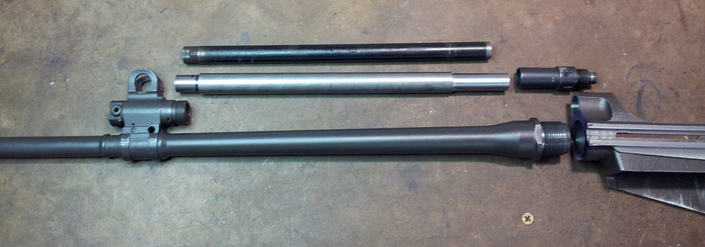
So that's what I did.
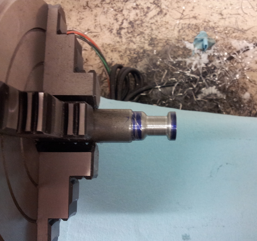
The photo above shows the solid gas "tube" with its rear section relieved to fit inside the gas nut, but that wasn't its final form. Using an original gas nut was clearly far too easy to be a viable option.
Gas "Tube" "Nut"
Remember how I mentioned that fixing the barrel alignment introduced two new dimensional problems? The first of those appeared when trying to assemble the barrel with the solid gas piston tube and original barrel nut. It wasn't that the solid piston tube rod had trouble fitting into the gas tube nut; there was plenty of clearance. Instead, moving the barrel up caused it to interfere with the gas tube nut, which could no longer be screwed in. Sanding, grinding, or milling down the underside of an existing gas tube nut wasn't an option because I didn't want to ruin a serviceable part to make up for my own mistake; besides, the amount of material to remove might end up breaking through the hollow nut.
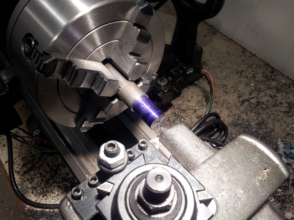
The only options remaining were to go without a gas tube nut or make one myself and relieve the bottom for clearance. The former option was aesthetically unthinkable, so I fired up the lathe. The pictures below show the process.
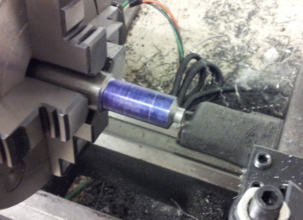
Turned to max diameter with areas laid out.
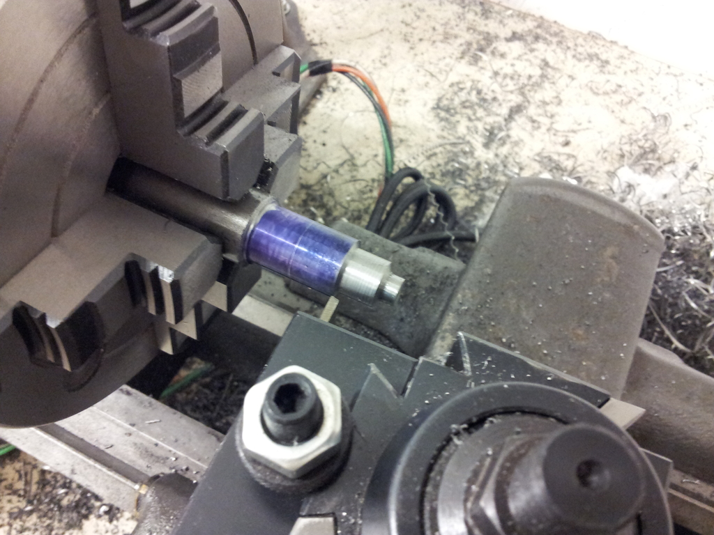
About to cut thread relief after turning to major diameter.
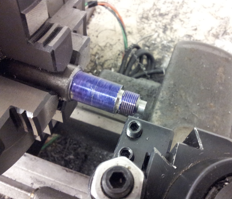
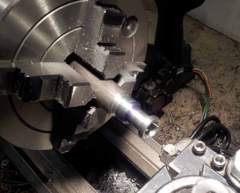
Just starting to thread.
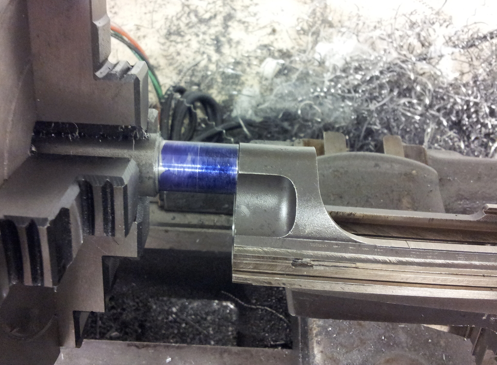
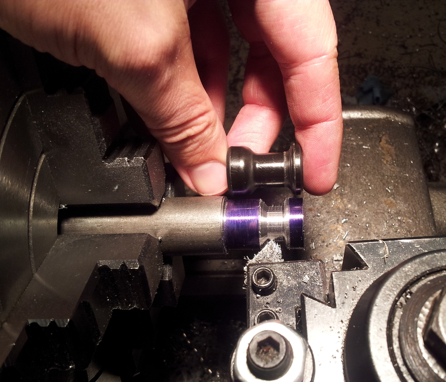
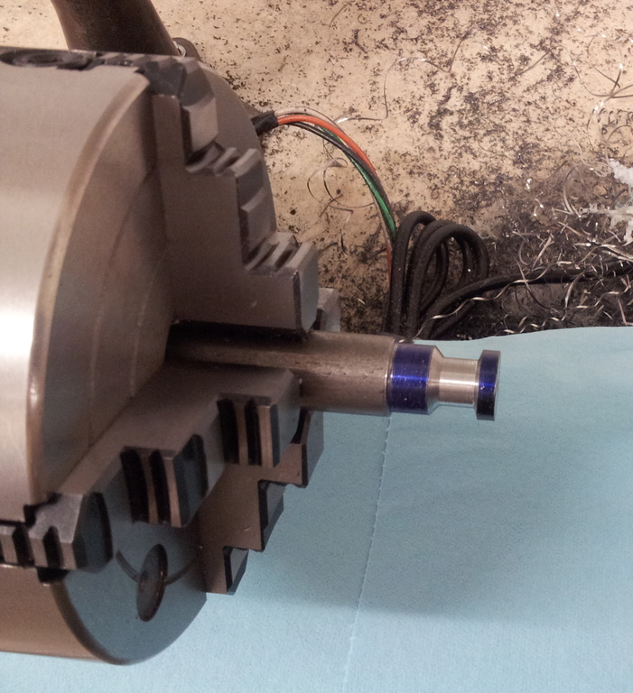
Testing threads prior to investing any more time.
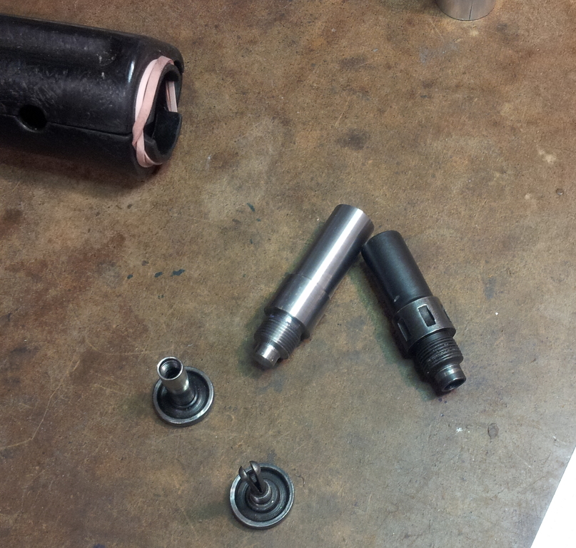
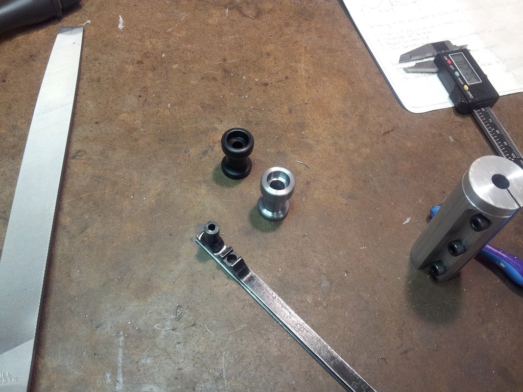
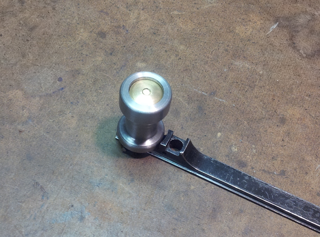
One of these things is heavier than the other.
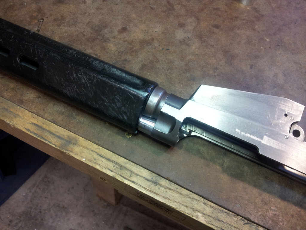
At this point, the self-fabricated gas tube nut was radially symmetrical, as befits something made on a lathe. That meant it had the same interference problems with the barrel that the OEM version did. I very briefly considered using a rotary table to achieve geometrically perfect relief of the area next to the barrel when fully screwed in, but en route to where the rotary table was kept detoured instead to the belt sander and just did it freehand. Surprisingly, it turned out well.
"Cleaning Kit"
One of my many FAL parts kits came with a pistol-grip cleaning kit which ended up in a neglected corner of the parts box because I have no use for it. However, it came to mind while staring at the empty pistol grip and ruing how little empty air weighed. The tiny lightbulb flickered feebly to life, I dug out the pistol grip cleaning kit, grabbed a handful of #7 lead shot, and promptly covered the shed floor with slip-inducing lead spheres. Eventually, though, enough shot ended up in the kit to lend it some mass, and eventually I cleaned enough shot off the floor to avoid face-planting onto machine tools.
Get the lead in.
"Recoil Spring"
The .22 conversion unit fits inside the receiver and includes its own spring, so there was no need for standard FAL recoil springs, especially seeing as how springs are mostly empty space and therefore weigh far too little. The obvious call was to replace the recoil spring assembly with a solid steel rod turned down to fit inside the tube. It was briefly tempting to turn some 12L14 into a solid recoil spring tube, but the specter of single-pointing both external and internal threads made that unappealing. Besides, the recoil spring tube fits through holes in the buttstock, so its external diameter can't be increased.
The remaining option consisted of turning down a steel rod to replace the spring assembly, which I did. I'm only going into this much detail on the subject because, in the interests of economy, I used a bar of hardware store grade steel as the raw materials. The precise type of steel was not disclosed on the label, but its alloying elements probably included silicon, carbon, and taffy. The combination of gummy steel and long unsupported length produced a result best hidden away inside the butt of a rifle.
Even parkerizing can't make it look good.
Far from being useless, the rod of soft mystery steel would come in handy for a later custom-made weight-enhancing component.
Charging Handle Knob (Actually A Charging Handle Knob)
A steel charging handle knob doesn't add that much weight over its plastic or aluminum alternatives, but a few extra ounces wouldn't hurt and I had always wanted to try making a charging handle knob. Also, the prospect of saving $10 by spending several hours of precious free time was too good to pass up.
It actually was pretty fun. The external dimensions are non-critical and are shaped in part with lathe filing, which was equal parts fun and hair-raising. The feel of the chuck stirring air underneath one's left arm tends to focus one's attention.
Major diameter cut and rough dimensions laid out.
The resemblance is uncanny!
Starting to vaguely resemble a charging handle knob. (Except for the lathe attached to it.)
Initial efforts to minimize blood loss while charging the rifle.

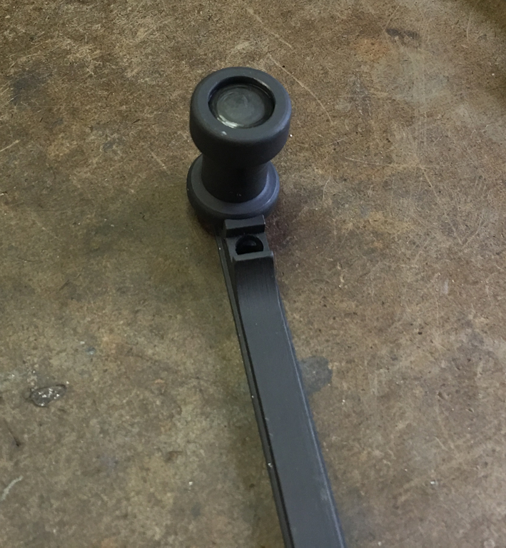
After final filing and sanding.
It's worth noting that at this point the charging handle knob was still entirely solid. I didn't bore it until later in order to ensure maximum rigidity during filing.
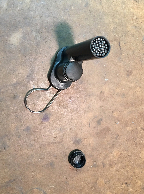
But once filing is done it's fair game.
The knob looked great and was fun to make. The shiny bare steel looked and felt so nice that I started pricing out stainless steel rod before I came to my senses.
Artisanal craftsmanship vs. soulless injection molding.
Still, residual desire for shininess inspired a brass nut-and-screw alternative to the traditional rivet.
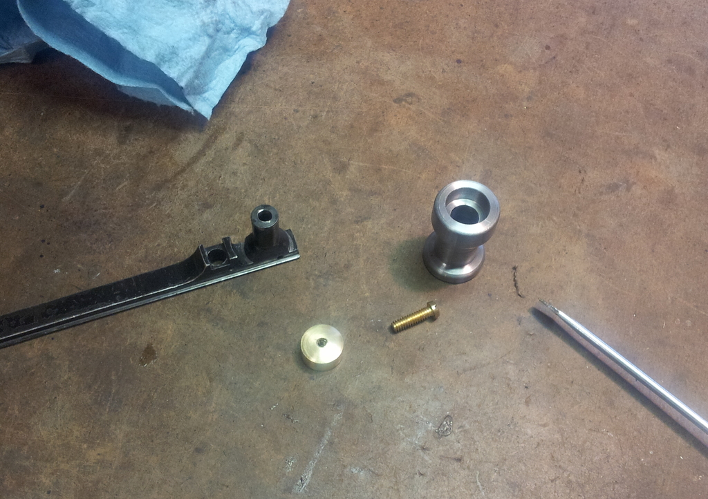
Doubly shiny.
The brass nut and screw lasted until the knob was parkerized, at which point the contrast between the brass and parkerizing became distasteful. (Besides, I'd hate to be accused of making a steampunk FAL.) I decided to rivet the knob in place, but rather than use up a viable rivet, I'd make my own. Canny readers may detect a recurring theme here.
That's where the gummy hardware-store steel made its reappearance. It seemed well-suited to the role of something intended for squishing and, like the knob, I'd always wanted to try making one.
I started by indicating the hot-rolled outer surface of the rod as best as possible. The difference in diameters between the rod and the rivet permitted over a tenth of an inch runout, but on general principle I got it to about five thousandths before starting to cut.
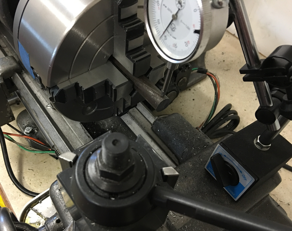
Initial facing and turning down to bare metal shows how poorly this steel cuts.
Making the rivet was fun for many of the same reasons that making the charging handle knob was fun: The dimensions were relatively noncritical, the lengths of cut were short, the work was rigid, and the result could be verified before removing it from the chuck.
If it doesn't need layout dye, I'm not interested.
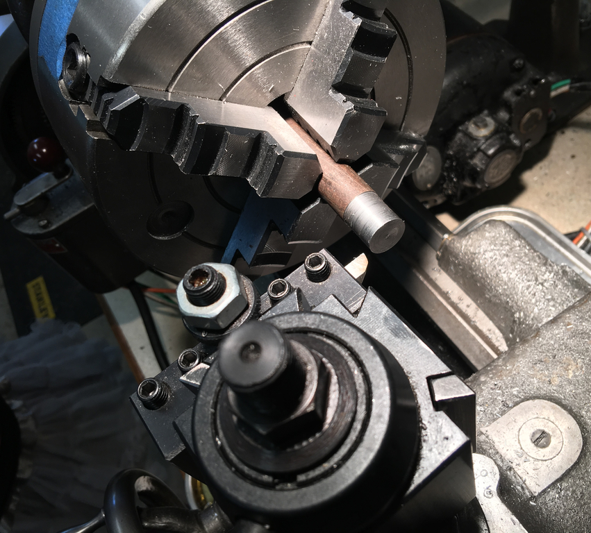
Note center drilled base of rivet to make flaring easier.
In the above photo, the finished surface closest to the chuck had a tangential shear tool used for the final pass to see if this cutter, renowned for its ability to provide a fine surface finish, would be able to make taffy steel look good. Impressively, it did.
Lathe turned off prior to this photo as evidenced by the lack of cameraman blood.
The rivet had been turned from the thin tail toward the area that would eventually be its head, which meant that after cutting off the rivet the head was flat. I wanted to mimic a typical domed rivet head, but lathe filing or contouring such a small part so close to the chuck smelled like the recipe for a mangling. Instead, I chucked up the rivet in a hand drill and used the running hand drill and belt sander to contour the rivet head.
If you ever use this technique, you may find it useful to know in advance that it will produce an obscenely hot rivet which should not, say, be dropped directly into one's palm when unchucked from the drill.
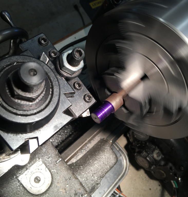
Rivet prior to aluminum oxide blasting and black oxide dip.

Attractive machining hidden by attractive black oxide finish.
After a quick dip in cold black oxide solution, the rivet was put to its eponymous purpose. I supported the rivet on an appropriately-sized wrench socket padded with thick felt and paper, then flared and peened the tail using a hammer and roll pin punch. Despite efforts to the contrary, the rivet ended up getting slightly marred by the socket, necessitating some touch-up work.
Still better than brass.
Summary
Some of the most enjoyable parts of the entire project involved replicating OEM parts, or coming up with a heavier alternative. Rather than struggling to correct earlier mistakes, each of these parts contributed to the final goal of enhancing weight or obviated the need to use or modify components which could be put to use in a .308 rifle. There's something satisfying about taking a solid chunk of metal and making it resemble a part that one has always associated with a professional product...then hitting it with the belt sander until it fits.
email: hidi.projects at gmail.com